Zones
A zone is an area whose heating is under control of one time and one temperature controller, i.e. one timer and one thermostat, or one programmable thermostat. For example heating in a large house may be divided into one zone comprising living rooms and another zone comprising bedrooms, with a timer and room thermostat (or programmable thermostat) for each zone.
Underfloor heating is usually run as a separate zone from radiators.
Where Domestic Hot Water is heated by the boiler the water heating may be considered as a zone.
Always-on/Bathroom radiators
In some older systems it was common for the bathroom radiator to be connected across the flow and return pipework to the hot water cylinder, keeping the bathroom warm and towels hung over the radiator dried and warmed at all times. Where DHW is heated by gravity circulation the pipework to this radiator had to be arranged to allow gravity circulation through the radiator: typically the radiator would have a flow connection at the top and return at the bottom.
In some fully-pumped systems one radiator (often in the bathroom) was arranged to be open at all times (with lockshield valves on both connections) so as always to provide a path for hot water even if all other radiators are closed. In S-plan systems or where the boiler manufacturer specifies a bypass loop such an always-on radiator may be connected directly across the boiler flow and return, before the zone valve(s).
As a matter of design choice a bathroom towel radiator can be connected directly across boiler flow and return, before zone valves, to allow towels to be dried and warmed when either space heating or DHW re-heating is in operation. As long as the radiator is not acting as a mandatory bypass for the boiler it can be fitted with a TRV so that it does not waste heat in hot weather.
Zone control configurations
One zone
The simplest arrangement for a small house or flat with a combi boiler is to have all the radiators heated at the same time under control of TRVs and (usually) a room thermostat linked to the boiler (if the boiler has a time control built-in) or a programmable thermostat (which provides time and temperature control in one unit).
CH and DHW zones: Y-plan
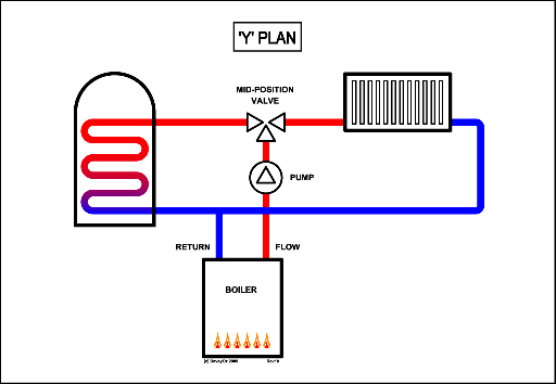
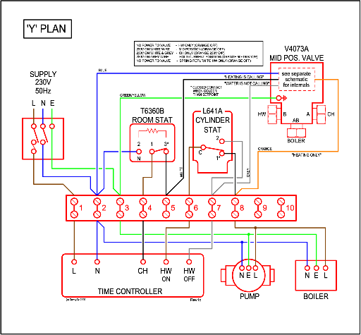
Where Domestic Hot Water is provided from a cylinder (or similar) it is necessary to control the flow of primary water heated from the boiler so that the cylinder can be heated without the radiators (and vice versa). The usual arrangement in this case uses a 3-port "mid-position" Motorised Valve to direct the pumped flow from the boiler to either the central heating circuit or the hot water cylinder, or both simultaneously. This is known as a Y-plan system.
Schematic
Wiring
CH and DHW zones: S-plan
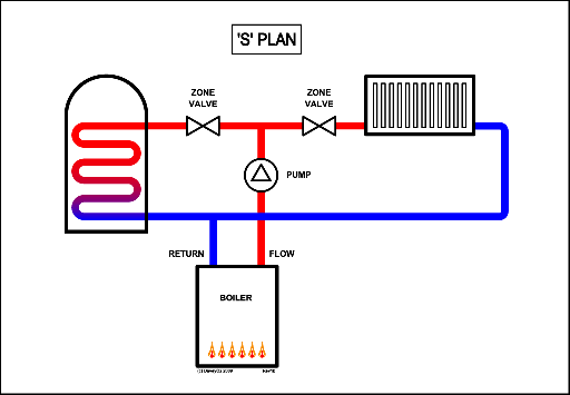
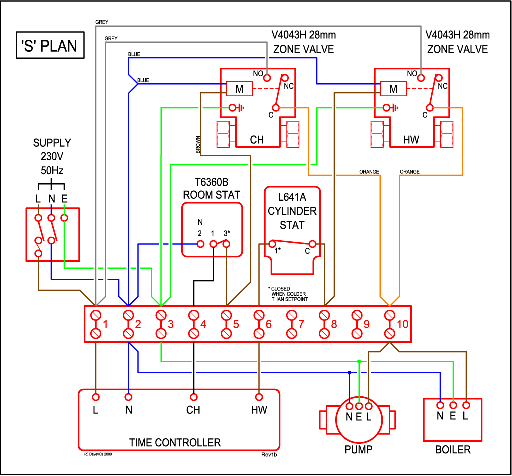
An alternative to the arrangement described in Y plan above, uses two 2 port zone valves in place of a single three port valve. This achieves a similar level of control as a Y plan system, but allows for further expansion into multiple heating zones at a later date (say to include discretely controlled under floor heating). One complication of a S-Plan system is that the boiler will need a separate bypass to allow water to pass through the system when all the valves are closed.
Schematic
Wiring
Multiple heating zones: S Plus-plan
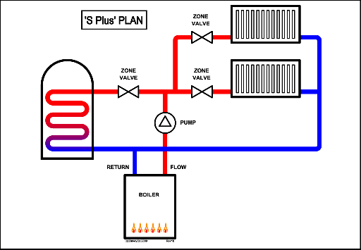
This is an extension of the S-Plan arrangement described above. For houses with floor areas above a certain size building regulations require that the space heating is divided into multiple zones. In a conventional house layout the upper floor (bedrooms etc) is connected as one zone and ground floor as another. Each zone is controlled by its own thermostat (as well as TRVs where appropriate). Since larger houses will usually have stored hot water systems this will also require independent control. Where some parts of a CH system use Underfloor Heating and others use radiators the UFH is usually run as a separate zone. It may also be appropriate to treat kickspace heaters as separate zones.
In these cases 3 (or more) 2-port Motorised Valves are used connected in an S-plan configuration.
Schematic
Wiring
Note that the wiring for this plan is effectively the same as for S-Plan, but with additional thermostat and zone valve for each additional zone.
Bypass Valves
When demand from all the zones in an S-plan system has ceased and the zone valves have closed the boiler may still need to run on for a while to dissipate heat in its heat exchanger. In this case it is necessary to fit a bypass valve directly between the flow and return, before the zone valves. In older installations a gate valve was usually used, sometimes a type which could only be operated by a square-head key rather than having a wheel-head. This was adjusted to try to allow sufficient flow to let the boiler dissipate heat when the zone valves were closed, without diverting too much flow away from the heating circuits when the valves were open. In modern installations an automatic bypass valve is mandated. These let water flow from flow to return when the pressure generated by the pump is high due to the zone valves being closed, but don't pass a flow when any of the zone valves are open.
Gravity DHW: C-Plan
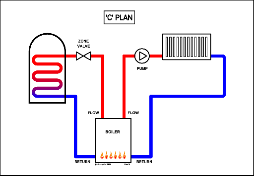
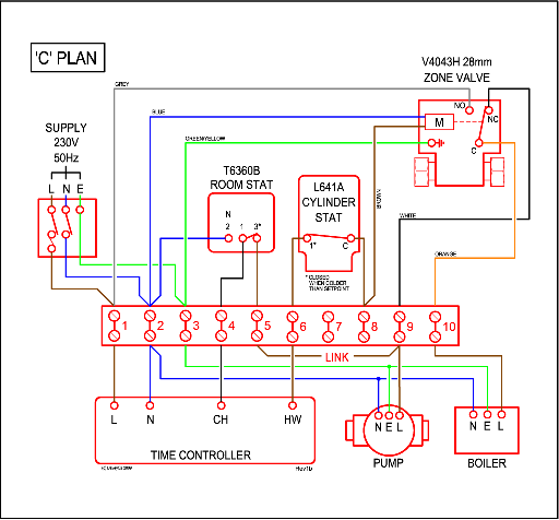
Older systems may be found to have gravity circulation to the DHW cylinder controlled by a 2-port (usually 28mm) zone valve in a C-plan system.
Schematic
Wiring
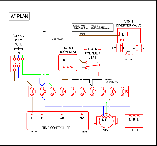
DHW priority: W-Plan
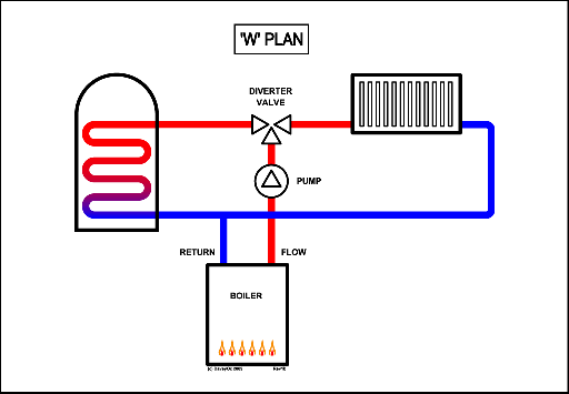
A variation on Y-Plan uses a 3-port Diverter (rather than Mid-Position) valve which switches all flow to either DHW or CH, never to both simultaneously. This is suitable for use with fast recovery DHW systems and is known as W-plan
Schematic
Wiring
Pump Plan
An alternative to using motorised valves to control the flow from a single pump is to use multiple pumps, one driving each zone. A packaged 2-zone Pump Plan system is available from Grundfos [1]. Pump Plan systems can also be constructed from individual components for two or more zones.
Timers, programmers, thermostats, programmable thermostats
- location of thermostats
- hall or living room - no external heat sources
Additional Thermostats
Some houses have areas with quite different heat loss profiles. One example would be a partly underground building, where the upper storeys are exposed to exterior air temperature, but the underground floors are exposed to near constant soil temp all year round. Conventional heating control setups can not deal effectively with wide variations in relative heat output between areas. TRVs improve the situation, but they can not balance a system effectively, as too large an air temp variation is needed to achieve the large degree of flow modulation these situations require.
For such applications, 2 or more thermostats are required, one controlling the heat in each zone. Generally one timer will control both areas.
TRVs
A Thermostatic Radiator Valve varies the flow of heating water through a radiator according to the temperature of a sensing element in the head of the valve (usually: a few models are available with remote sensing elements). This gives an approximation to control of the room temperature. Although the control is far from perfect TRVs are a great improvement over manual valves for maintaining comfortable room temperatures in an energy-efficient way.
Bidirectional TRVs
A result of the design of TRVs is that they are liable to cause water hammer if fitted the "wrong" way round with respect to the flow of water through them. Most modern TRVs are designed to minimise the probability of this occurring and are described as bi-directional. One model (Danfoss' RAS-C revolver) has a design which allows the flow through the valve to be easily switched to the correct direction.
Where to fit TRVs
TRVs may be fitted to all radiators except at least one in the area sensed by the zone thermostat. Where only a few TRVs can be fitted (for whatever reasons) the greatest benefit is likely to be gained by fitting them to bedrooms (with the largest, hardest to heat first) followed by large halls and stairways, and WCs. All these can ideally be run at lower temperatures than main living areas so using TRVs to maintain lower temperatures saves more energy.
In a standard system if TRVs are fitted to all radiators and there is no room thermostat then energy will be wasted by the boiler cycling when all rooms are up to temperature. (There are, however, unusual systems employing thermal stores or other measures in which an all-TRV setup is intentional and energy-efficient.) The same problem can occur if TRVs are fitted to all radiators in a system that does have a room thermostat: if the TRV in the area with the thermostat closes down while the thermostat is still calling for heat it will continue to keep the boiler firing even when all the TRVs are closed.
TRVs and balancing
Fitting TRVs to radiators is not a substitute for properly balancing a system. They can mask, and to some extent ameliorate, the effects of poor balance.
Mixed Radiator and Underfloor layouts
UFH needs to be run at temperatures (circa 30°C) well below those used in radiators (c. 80°C). The standard way of reducing the temperature of water in mostly radiator systems uses a thermostatic mixing valve and a separate pump to circulate the UFH loop. Various cheaper schemes exist using e.g. a thermostat which blocks flow from the main CH pipework to the UFH when the UFH is up to temperature. Where a thermal store or heat bank is used to supply space heating it is often arranged with a take-off loop towards the bottom of the store supplying water at lower temperatures suitable for the UFH.
Special controls
Generally available controls are On/Off: they control the boiler with Demand or No-Demand signals.
Proportional controls (with analogue sensors) are available with some high-end boilers. They tell the boiler what the current temperature is so the boiler can determine how much heat to produce to acheive the desired temperature.
Weather compensation controls are also available with some boilers: an outdoor temperature sensor provides advance warning to the boiler of the likely heat demand of the building.
